
Electrical and electronics symbols are graphical representations of components used in circuits. They enable clear communication in circuit design and analysis, standardizing understanding across industries and education.
Importance of Electrical and Electronics Symbols
Electrical and electronics symbols are fundamental for clear communication in circuit design and analysis. They standardize the representation of components, ensuring consistency across industries and educational materials. These symbols simplify complex circuits, making it easier to understand and troubleshoot designs. They also facilitate collaboration among engineers and technicians worldwide. In education, symbols aid students in grasping electrical concepts visually. Industries rely on them for precise documentation, reducing errors in manufacturing and maintenance. Additionally, symbols enhance safety by providing universal recognition of components, crucial for avoiding hazards. Their importance extends to both theoretical and practical applications, making them indispensable in modern electrical and electronic engineering.
Common Electrical and Electronics Symbols
Common symbols include resistors, capacitors, inductors, and diodes, each representing specific components in circuits. These universal symbols simplify circuit understanding and design across industries and education.
Resistors
A resistor is a passive electrical component that opposes the flow of current in a circuit. It is represented by a unique symbol in circuit diagrams, ensuring clarity in design and analysis. Resistors are available in fixed and variable types, with materials like carbon film or metal oxide determining their resistance values. Fixed resistors have a constant resistance, while variable resistors, such as potentiometers and rheostats, allow for adjustable resistance. In schematics, resistors are often labeled with their resistance value and tolerance. They play a crucial role in voltage division, current limiting, and signal attenuation, making them essential in electronic circuits. Their standardization ensures consistency across industries and educational resources.
- Resistors are fundamental in circuit design.
- They are available in various types and materials.
- Their symbols and values are standardized for clarity.

Capacitors
A capacitor is a passive electrical component that stores electric charge, consisting of two conductive plates separated by an insulating material; Its symbol in circuit diagrams represents this structure, with parallel lines denoting the plates. Capacitors act as a short circuit for alternating current (AC) and an open circuit for direct current (DC). They are categorized into fixed and variable types, with fixed capacitors having a constant value and variable capacitors allowing adjustment. Polarized capacitors, such as electrolytic types, require proper voltage polarity. Their ability to store and release energy makes them essential for filtering, coupling, and energy storage applications. Capacitors are fundamental in electronic circuits, and their standardized symbols ensure clear representation in schematics and designs.
- Capacitors store electric charge in circuits.
- They are categorized into fixed, variable, and polarized types.
- Their symbols vary slightly based on type and polarity.
Inductors
An inductor is a passive electrical component that stores energy in a magnetic field when current flows through it. Its symbol represents coiled wire, indicating its typical construction. Inductors oppose changes in current, a property known as inductance, measured in henries. They are used for filtering, tuning, and storing energy in circuits. Fixed and variable inductors exist, with variable types allowing adjustment. Air-core inductors have no core material, while iron-core inductors increase inductance. The standardized symbol ensures consistency in circuit diagrams, helping engineers and technicians understand designs globally. Inductors are crucial in applications like radio tuning, power supplies, and noise reduction, highlighting their importance in modern electronics.
- Inductors store energy magnetically.
- They are represented by a coiled wire symbol.
- Types include air-core, iron-core, and variable inductors.
Diodes
A diode is a semiconductor component that allows current to flow in one direction while blocking it in the opposite direction. Its symbol features an arrow pointing toward a vertical line, representing the direction of conventional current flow. Diodes are essential in applications such as rectification, signal demodulation, and voltage regulation. The standard diode symbol is widely recognized in circuit diagrams, ensuring clarity in design and analysis. Specialized types, like Zener diodes, have unique symbols and functions, such as voltage regulation. Diodes are fundamental in electronic circuits, enabling the control of current flow, which is crucial for many modern technologies.
- Diodes allow unidirectional current flow.
- The symbol features an arrow and vertical line.
- Specialized types include Zener and Schottky diodes.

Specific Electrical and Electronics Components
This section covers detailed symbols for transformers, motors, meters, and switches. These components are crucial for power conversion, measurement, and control in electrical circuits and systems.
Transformers
The transformer symbol represents a device that transfers electrical energy between circuits through electromagnetic induction. It consists of two or more coupled windings wrapped around a common core. The transformer symbol typically shows two coils on either side of a rectangular or oval core, indicating primary and secondary windings. This component is essential for voltage step-up or step-down in AC circuits. The symbol may vary slightly to denote specific types, such as auto-transformers or isolation transformers, but the basic structure remains consistent. Transformers play a vital role in power distribution and are widely used in electrical systems. Their symbols are standardized to ensure clarity in circuit diagrams.
Motors
The motor symbol represents a device that converts electrical energy into mechanical energy. It is depicted as a circle with an “M” inside, often attached to a rectangle, indicating the motor’s mechanical output. This symbol is widely recognized in circuit diagrams. Motors are essential in various applications, from industrial machinery to household appliances. The symbol may vary slightly for different types, such as AC or DC motors, but the core representation remains consistent. Standardization ensures clarity in electrical designs. Motors are crucial for driving mechanical loads, making them a fundamental component in many systems. Their symbols are universally adopted to simplify circuit understanding and design processes across industries and education.
Meters (Voltmeter, Ammeter)
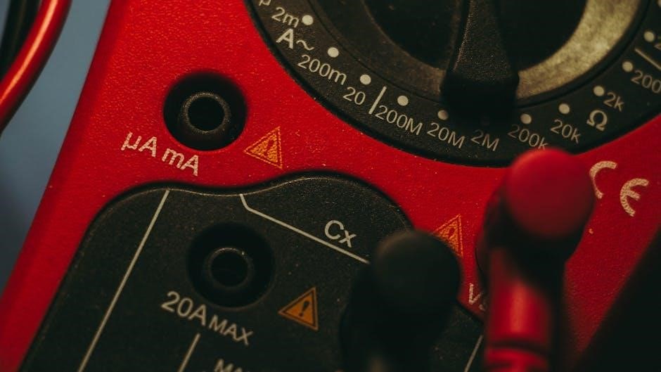
Meters are essential components in electrical circuits, used to measure voltage, current, or other electrical parameters. The voltmeter symbol is represented by a “V” inside a circle, while the ammeter symbol features an “A” within a circular shape. These symbols are standardized to ensure clarity in circuit diagrams. Voltmeters measure voltage across a component, whereas ammeters measure the current flowing through a circuit. Both are critical for diagnosing and analyzing electrical systems. Their symbols are universally recognized, simplifying communication among engineers and technicians. Meters are indispensable tools in both education and industry, providing precise measurements that are vital for circuit design, troubleshooting, and performance optimization.
Switches and Fuses
Switches and fuses are fundamental components in electrical circuits, represented by distinct symbols. A switch symbol resembles a simplified breaker, indicating its function of controlling current flow. Fuses, depicted by two terminals with a breaking point, act as protective devices that interrupt the circuit during overcurrent conditions. These symbols are standardized to ensure universal understanding. Switches allow manual or automatic control of power supply, while fuses provide critical protection against short circuits or overload. Their symbols are essential in circuit diagrams for clear communication among engineers and technicians. Both components are vital for ensuring safety and efficiency in electrical systems, making them indispensable in both industrial and educational contexts.

Standards and Sources for Electrical Symbols
Standards like the Institution of Electrical Engineers’ booklet and BS 3939 provide authoritative sources for electrical symbols, ensuring consistency and clarity in their application globally.
Institution of Electrical Engineers (IEE) Booklet
The IEE booklet, published in 1968, serves as a foundational guide for electrical and electronic engineering symbols. It provides standardized representations for components like resistors, capacitors, and inductors, enhancing clarity and consistency in circuit designs. This resource is widely recognized for its comprehensive coverage, making it an essential tool for both educational and professional use. By adhering to these standards, engineers and students ensure accurate communication of electrical concepts. The booklet remains a trusted reference, contributing to the universal understanding of electrical and electronic systems.
BS 3939 Electrical Symbols
BS 3939 outlines standardized electrical symbols for use in engineering and design. These symbols, widely adopted in the UK, cover components such as switches, fuses, and transformers. They ensure consistency in circuit diagrams, enhancing readability and reducing errors. The standard is regularly updated to reflect technological advancements, making it a reliable resource for professionals. By using BS 3939 symbols, engineers can effectively communicate designs across industries, ensuring compliance with national standards. This standardization is crucial for maintaining safety and efficiency in electrical systems, making it a cornerstone of modern electrical engineering practices.
Downloading Electrical and Electronics Symbols as PDF
Electrical and electronics symbols are widely available as downloadable PDFs. Resources like BS 3939 and technology student websites offer free PDFs for easy access and reference.
Steps to Download Symbols as PDF
To download electrical and electronics symbols as PDF, visit reputable sources like BS 3939 or technologystudent.com. Search for “electrical symbols PDF” and select a reliable document. Click the download link to save the file. Ensure the PDF includes components like resistors, capacitors, and transformers. Verify the source for accuracy and completeness. These resources are invaluable for education, design, and industry applications, providing standardized symbols for clear communication in circuit diagrams and electronics engineering.
Applications of Electrical and Electronics Symbols
Electrical and electronics symbols are essential in circuit diagrams, enabling clear communication of component functions. They are widely used in education and industry for designing, analyzing, and troubleshooting electrical systems.
Use in Circuit Diagrams
Electrical and electronics symbols are fundamental in creating circuit diagrams, providing a standardized visual language for engineers and technicians. These symbols represent components like resistors, capacitors, and inductors, ensuring clarity and consistency. By using these symbols, circuit diagrams become universally understandable, facilitating collaboration across different regions and industries. They simplify complex circuits, making it easier to identify and connect components. Proper use of symbols in circuit diagrams aids in troubleshooting, design verification, and documentation. This standardized approach minimizes errors and enhances the efficiency of electrical and electronic systems’ development and maintenance. As a result, circuit diagrams are indispensable tools in both educational and professional settings.
Importance in Education and Industry
Electrical and electronics symbols are vital in education and industry, serving as a universal language for understanding circuit designs. In educational settings, these symbols help students grasp fundamental concepts of electronics, enabling them to interpret and create circuit diagrams. In industry, they ensure precise communication among engineers and technicians, reducing errors in design and implementation. Standardized symbols facilitate collaboration across global teams, fostering innovation and efficiency. They also play a critical role in training professionals, ensuring a skilled workforce for advancing technologies. The consistent use of these symbols supports the development of safe and reliable electrical systems, making them indispensable in both academic and professional environments. Their importance cannot be overstated in driving progress and maintaining high standards in the field.